Wendell Hostetler 33% Gee Bee R1-2
This Wendell Hostetler Gee Bee R-2 is going to be modified into the long tail version R1-2. The short kit was provided by National Balsa and will be the first time I have built one of their laser cut kits. Having done laser cutting myself, I have to admit that I am not all that impressed with this short kit. The material quality is nuts on but the laser cutting leaves a bit to be desired…more details in the descriptions below. Follow along with this not so often modeled long tail Gee Bee R1-2.
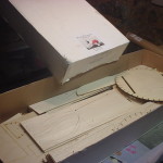
GeeBeeR1-2-001
You gotta love the little Gee Bee.
GeeBeeR1-2-002
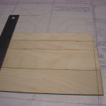
The material in the National Balsa short kit is of good quality.
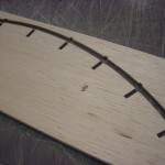
GeeBeeR1-2-003
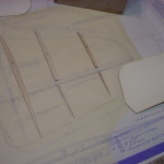
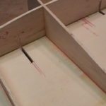
I have a feeling these stringer notches are going to need deepened when the time comes.
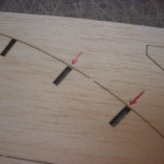
GeeBeeR1-2-004
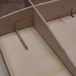
I also get the feeling these will be too deep. Sloppy CAD work sent to the laser cutter is my guess.
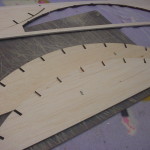
GeeBeeR1-2-005
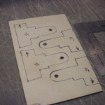
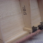
Here are 2 parts marked with the same part number that are clearly different. I'll figure this one out when it comes time to build the fuselage.
GeeBeeR1-2-006
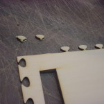
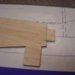
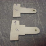
The necks on these alignment tabs are entirely too small and there are too many of them. There were a dozen or so broken off when I received the kit as well as a few that I broke off separating the parts.
GeeBeeR1-2-007
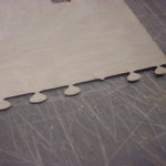
More broken tabs on the 1/32" plywood.
GeeBeeR1-2-008
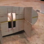
The front spar joiner boxes are 1/4" too long according to the plan.
GeeBeeR1-2-009
All of the ribs are 3/16" too long according to the plan.
GeeBeeR1-2-010
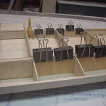
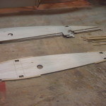
The front and rear spar joiner box sides should all be the same length. Not only are they not the same length, but none of them are the correct length.
GeeBeeR1-2-011
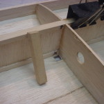
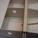
The ribs at the aileron bay had no seat for the rear spars to keep them spaced properly. I've added one to all of the ribs similar to the one shown here.
GeeBeeR1-2-012
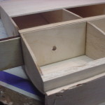
Alright, enough bitchin and moanin...time to get to work. Right front spar joiner box epoxied up.
GeeBeeR1-2-013
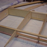
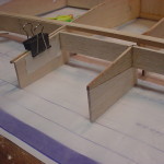
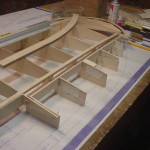
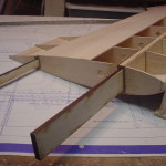
Right outer spar joiner boxes in place as well as the first aileron bay rib.
GeeBeeR1-2-014
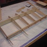
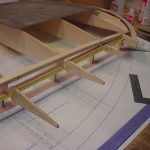
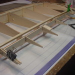
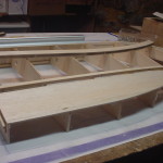
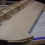
Ribs and front shear webs in place. You can see the large amount of washout built into this wing.
GeeBeeR1-2-015
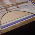
Starting the tip construction.
GeeBeeR1-2-016
I built the top and bottom of the tips right onto rib W-8 prior to gluing it in place.
GeeBeeR1-2-017
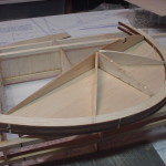
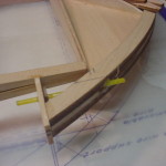
Wing tip assembly glued in place. There is no clear detail on the plans of how to handle the ends of the rear spars. For now I've tapered the bottom of the top spar and epoxied it to the bottom spar. The top will need further shaping later.
GeeBeeR1-2-018
Adding a light balsa filler piece to the top of the rear spar.
GeeBeeR1-2-019
Filler piece sanded to the contour of the ribs. The front spar will get the same treatment.
GeeBeeR1-2-020
Laying out the aileron hinge pin location.
GeeBeeR1-2-021
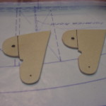
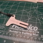
The traced W-7 aileron rib per plan versus the laser cut part below.
GeeBeeR1-2-022
Aileron ribs, hinge pin, and inner nyrod guide tube dry fit together.
GeeBeeR1-2-023
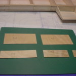
I use 3/32" aircraft ply for the hinges in lieu of the formica that the plans call for. I guess I can't fault National Balsa for this one since Wendell calls for formica.
GeeBeeR1-2-024
Hinge plates cut out on the scroll saw with nyrod bearings glued in.
GeeBeeR1-2-025
Nyrod bearing tube through the wingtip assembly. The hinge pin will be inserted from this end.
GeeBeeR1-2-026
I epoxied a small ply reinforcing plate on the inner rib where the hinge pin will end.
GeeBeeR1-2-027
3/32" aircraft ply control horns cut out on the scroll saw. Again, the plans call for formica but I feel that these should have been included with the short kit.
GeeBeeR1-2-028
Aileron parts dry fitted again. Not sure how to keep all of this straight since the cutter didn't provide jig tabs on the aileron ribs.
GeeBeeR1-2-029
Only right way to do it is make the jig tabs. Building this wing panel is somewhat complicated by the amount of washout that is incorporated.
GeeBeeR1-2-030
All jig tabs made up and ready to glue up the aileron.
GeeBeeR1-2-031
It was decided to go with concealed linkages on the ailerons so I've removed the little ply plate reinforcement and added a new hinge location that will allow room for a torque rod setup. The plywood control horn will be removed later.
GeeBeeR1-2-032
Aileron back in position with the new end hinge point.
GeeBeeR1-2-033
Aileron top sheeting applied.
GeeBeeR1-2-034
aileron trailing edge added.
GeeBeeR1-2-035
The area of the top rear spar with the pencil scribbles has to be carved/sanded down to form the wingtip.
GeeBeeR1-2-036
And here is the spar after shaping.
GeeBeeR1-2-037
Top sheeting started in the center of the rear spar to allow for an aileron gap shroud that will be added later.
GeeBeeR1-2-038
Enough top sheeting on to pull it off the table and inspect things underneath.
GeeBeeR1-2-039
Top sheeting completed and rough sanded.
GeeBeeR1-2-040
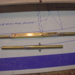
Quick mock ups of 2 possible configurations for the plug in torque rod assembly.
GeeBeeR1-2-041
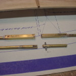
Plug in torque rod assemblies pulled apart.
GeeBeeR1-2-042
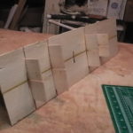
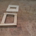
1/16" plywood shear webs sized to fit.
GeeBeeR1-2-043
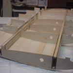
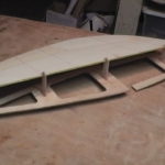
Plywood shear webs glued in place in the two rib bays beyond the spar joiner boxes.
GeeBeeR1-2-044
Hole cut in top sheeting for the flying wire hard point mount.
GeeBeeR1-2-045
The flying wire mounts are made from 3/8" sq. basswood in lieu of the dowel suggested on the drawings.
GeeBeeR1-2-046
Mounting blocks epoxied in place and then filleted with a mixture of epoxy and milled fiberglass.
GeeBeeR1-2-047
Top view of mounting blocks prior to sanding flush with the top wing sheeting.
GeeBeeR1-2-048
The space between the rear spars is filled in with 3/8" balsa but this looks a little crappy....
GeeBeeR1-2-049
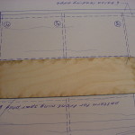
...so i covered the whole mess with 1/32" plywood. Once the ailerons and gap shrouds are mounted, you will never see this area but at least it looks good for now.
GeeBeeR1-2-050
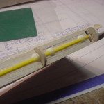
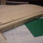
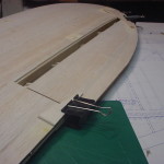
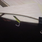
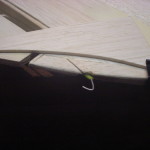
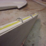
1/16" music wire hinge pin bent to final shape and notched into the wingtip.
GeeBeeR1-2-051
Hinge pin inserted all the way into the wingtip notch.
GeeBeeR1-2-052
In preparation for bottom sheeting, balsa filler was added to the spars and sanded to the wing contour.
GeeBeeR1-2-053
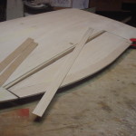
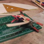
As a safety measure, I pinned a 1/4" balsa jig to the leading edge to make sure the washout doesn't get changed as I sheet the bottom of the wing panel.
GeeBeeR1-2-054
First piece of sheeting glued in place.
GeeBeeR1-2-055
In order to "pin" the spar joiners in place, I have to install them now before completing the bottom sheeting. The joiners are epoxied in place and then...
GeeBeeR1-2-056
...I've drilled a 1/4" hole through the joiner box assembly for the main spar.
GeeBeeR1-2-057
A 1/4" birch dowel is coated with epoxy and inserted through the spar box assembly.
GeeBeeR1-2-058
Birch dowels rough cut to length until the epoxy cures.
GeeBeeR1-2-059
Dowels sanded flush to the joiner box.
GeeBeeR1-2-060
Bottom leading edge sheeting completed.
GeeBeeR1-2-061
Laying out the torque rod position and additional needed parts.
GeeBeeR1-2-062
Ribs are notched out to allow the torque rod assembly to drop in place.
GeeBeeR1-2-063
I chose to use the square tube for the bearing tube in order to get a more positive lock in the plywood ribs.
GeeBeeR1-2-064
Torque rod/tube assembly trial fit in place.
GeeBeeR1-2-065
The torque rod is a 3/16" brass rod bent and inserted into a hardwood block which will be epoxied in the aileron.
GeeBeeR1-2-066
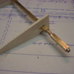
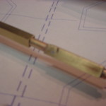
Square tube soldered to torque rod to make up the plug-in feature.
GeeBeeR1-2-067
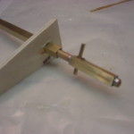
For added security I've drilled a 3/32" hole and inserted a tube through the soldered tube.
GeeBeeR1-2-068
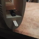
Hard to see here but the little silver dot is the 3/32" tube soldered in place and ground smooth.
GeeBeeR1-2-069
Every thing back in place for a final check fit.
GeeBeeR1-2-070
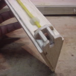
The hinge pin stops short of the end of the aileron to make room for the torque rod.
GeeBeeR1-2-071
I've cut a 1/8"x1/4" notch in the ribs for a spruce stringer.
GeeBeeR1-2-072
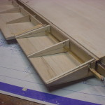
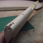
Stringer in place. This should help transfer the input from the torque rod throughout the length of the aileron.
GeeBeeR1-2-073
Framing up a pocket around the torque rod insertion point.
GeeBeeR1-2-074
A few epoxy/milled fiberglass bridges over the hinge tube to ensure they don't break loose from the CA glue.
GeeBeeR1-2-075
The aileron leading edge is sheeted with 1/8" balsa. To make things easier I am using 2 layers of 1/16" balsa.
GeeBeeR1-2-076
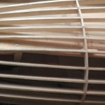
Starting the second layer of 1/16" sheeting with staggered joints.
GeeBeeR1-2-077
The aileron leading edge as built is rubbing the trailing edge of the wing so we are going to go at this a second time. This will also give me the opportunity to find and fix a slight bind in the aileron hinge pin.
GeeBeeR1-2-078
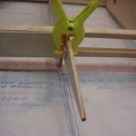
I made a balsa straight edge jig to check and make sure that the hinge pin is straight throughout the length of the aileron.
GeeBeeR1-2-079
Aileron clamped back in position to re-glue the nyrod hinge bearings.
GeeBeeR1-2-080
I am fairly certain the binding was located at the tip. I have cut out a section of the wingtip to allow the nyrod to float and find it's own straight path.
GeeBeeR1-2-081
Nyrod glued in place and the wingtip filled in with scrap balsa.
GeeBeeR1-2-082
A little black Sharpie on the end of the nyrod bearing will transfer a mark to....
GeeBeeR1-2-083
... the back of the 1/32" ply end cap to locate the hole properly.
GeeBeeR1-2-084
The right aileron is still giving me grief after rebuilding the second time so I am going to move on to the left wing outer panel. The hope is that the aileron problem areas will present themselves when I build the left side. Here i have glued some balsa stiffeners to the root rib before cutting out for the spar boxes. This will ensure that the root rib stays straight.
GeeBeeR1-2-085
Left wingtip assembly made up.
GeeBeeR1-2-086
I have added stiffeners to all of the rib jig tabs to help ensure they don't break off if I put too much pressure on the wing at any time.
GeeBeeR1-2-087
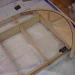
Left wing panel framed up.
GeeBeeR1-2-088
Close up of the rear spar where it meets the tip rib.
GeeBeeR1-2-089
Here I have glued the first row of top sheeting in place and carefully removed the wing from the board, turned it around to make working on the aileron easier, and pinned it back down to the board.
GeeBeeR1-2-090
The aileron ribs and their associated jig tabs have been dry fit in place.
GeeBeeR1-2-091
A lot of steps done to the left aileron here but the end result is that I have a better understanding of what went wrong with the right aileron. I had traced out a set of aileron ribs prior to gluing up the left side so that I can rebuild the right side properly.
GeeBeeR1-2-092
Close up of the left aileron at the wingtip. Much better fit and zero binding to boot.
GeeBeeR1-2-093
I have made a few jigs to get the right wing panel back on the board as it should be with the proper washout. These jigs were made using the left wing panel ribs as a template.
GeeBeeR1-2-094
Gathering parts to rebuild the right aileron. I will tear apart the original one and use the torque block and spruce spar...everything else gets trashed.
GeeBeeR1-2-095
Hopefully the third time is the charm.
GeeBeeR1-2-096
Right side aileron trailing edge and top sheeting in place.
GeeBeeR1-2-097
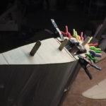
Torque block and spruce spar glued in place while keeping the aileron clamped to the wing. The bottom sheeting will be glued in place while clamped as well.
GeeBeeR1-2-098
Much better...I am finally happy with the right aileron and can move on.
GeeBeeR1-2-099
Now to take care of the fact that the aileron leading edge binds on the wing trailing edge. Simple fix of trimming the ribs a bit before sheeting.
GeeBeeR1-2-100
Making up the box around the torque rod. You can also see the epoxy / milled fiberglass bridges around the nyrods have been added.
GeeBeeR1-2-101
Starting the double layer of 1/16" balsa leading edge sheeting. Deja Vu?
GeeBeeR1-2-102
The aileron leading edge tips are a pretty small radius to be sheeting so I filled the end in with solid balsa...
GeeBeeR1-2-103
...and carved / sanded to shape.
GeeBeeR1-2-104
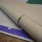
1/32" plywood end caps on the ailerons...
GeeBeeR1-2-105
...and on the wing at the aileron opening.
GeeBeeR1-2-106
Gathering material for the aileron gap shrouds. They will be made from laminated 1/32" plywood and 3/32" balsa to match the 1/8" wing sheeting.
GeeBeeR1-2-107
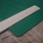
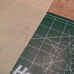
I drew a line about 1/4" back from one edge to help keep the taper consistant.
GeeBeeR1-2-108
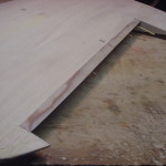
A little blurry but you can see the 3/32" balsa tapered up to the 1/32" plywood.
GeeBeeR1-2-109
Bottom shroud glued in place and sanded smooth with the contour of the wing.
GeeBeeR1-2-110
Aileron put in place to check for a consistent gap. I did some sanding to the aileron leading edge to get to this point.
GeeBeeR1-2-111
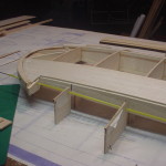
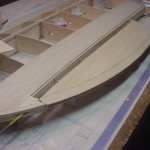
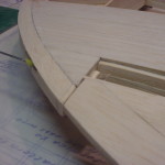
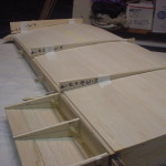
Shot of the wing trailing edge with both the top and bottom shroud in place.
GeeBeeR1-2-112
The final 1/4" balsa leading edge is glued to the sub leading edge / sheeting.
GeeBeeR1-2-113
Leading edge sanded to an airfoil shape.
GeeBeeR1-2-114
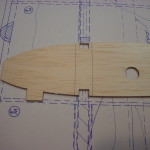
The plans clearly call for 1/32" plywood end caps on the wing panels so they should have been included in the National Balsa short kit but they were not. I've used a W-1 rib to lay out a piece that will span the 2 spar joiners and will finish off the front and back with scrap..
GeeBeeR1-2-115
1/32" root end cap in place.
GeeBeeR1-2-116
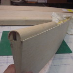
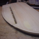
Finished right wing panel ready for final sanding.
GeeBeeR1-2-117
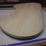
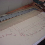
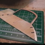
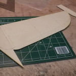
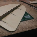
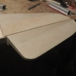
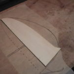
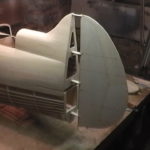
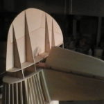
Horizontal stab re-drawn to a more scale outline.
GeeBeeR1-2-118
I guess the S-2 rib didn't need cut at the hinge line...not at all impressed with National Balsa's short kit.
GeeBeeR1-2-119
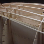
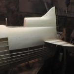
Setting the stab aside for a bit to start working on the fuselage. Modifying the Hostetler drawings to extend the tail for the R1/2 version.
GeeBeeR1-2-120
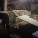
Fuselage side slabs all glued up. What a colossal pain in the ass to glue all of those little keying pins. These could have been cut in a much simpler pattern.
GeeBeeR1-2-121
Adding 7" to the fuse sides for the long tail. The slot will accept the horizontal stab core when the time comes.
GeeBeeR1-2-122
Matching top and bottom cross pieces all cut and ready to go.
GeeBeeR1-2-123
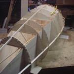
Main fuse box of this beast taking shape.
GeeBeeR1-2-124
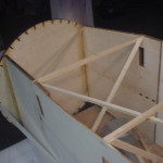
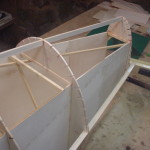
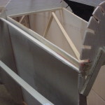
Lots and lots of temporary x-bracing. These will remain until after the fuselage is sheeted.
GeeBeeR1-2-125
Firewall epoxied in place.
GeeBeeR1-2-126
Shot of the rear of the firewall. There will be triangle stock added later to reinforce the glue joint to the fuse sides.
GeeBeeR1-2-127
Former F-2 added.
GeeBeeR1-2-128
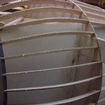
Stringers between F-1 and F-2 are laser cut parts.
GeeBeeR1-2-129
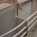
Stringers left out where the wing joiner box will go through the fuselage.
GeeBeeR1-2-130
Hatch formers at F-2 and F-3 cut and clamped in place. These formers were missing from the National Balsa short kit.
GeeBeeR1-2-131
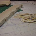
I was out of 1/8"x1/2" stick material so I made a quick balsa stripper. This little gadget turns a 1/8"x6" sheet into 12 strips in about a minute.
GeeBeeR1-2-132
Main side and bottom stringers in place to guage for straightness.
GeeBeeR1-2-133
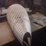
Formers F-1 through F-6 will be used as is from the short kit. Formers F-7 through F-9 will be re-cut to match the Haffke long tail plans.
GeeBeeR1-2-134
Transferring the Hostetler stringer locations to the Haffke former shapes proved to be futile. I ended up having to sight the stringers individually and re-cut slots as needed to straighten them up.
GeeBeeR1-2-135
The new former F-7 in place.
GeeBeeR1-2-136
New former F-8 glued in place at the rear of the fuselage sides.
GeeBeeR1-2-137
Closeup of a stringer tapering into former F-8.
GeeBeeR1-2-138
Stringer slot being re-cut and shimmed with 1/16" balsa.
GeeBeeR1-2-139
Former cut out for the wing joiner box.
GeeBeeR1-2-140
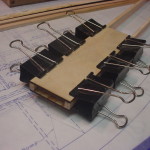
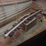
Rear spar joiner box glued up and clamped.
GeeBeeR1-2-141
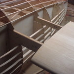
Joiner boxes in place, aligned, and ready for epoxy.
GeeBeeR1-2-142
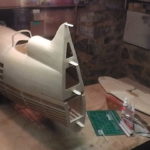
A shot with the wing outer panels in place. For size reference, the workbench is a 36"x80" door panel.
GeeBeeR1-2-143
Filling in the remaining stringers around the wing joiner boxes.
GeeBeeR1-2-144
All bottom half stringers in place.
GeeBeeR1-2-145
Moving on to the stub wings so I can mount the landing gear while still being able to level the fuselage by sitting it on its top side. Here I've added some 1/8" sq. balsa to the ribs so that they hold their shape...
GeeBeeR1-2-146
...when i make the cutouts for the spar boxes.
GeeBeeR1-2-147
Stub wing ribs in place.
GeeBeeR1-2-148
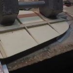
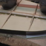
I plugged the wing panel in before gluing the end rib to ensure a tight fit to the outer panel. You can also see the leading edge in place here.
GeeBeeR1-2-149
Starting the top sheeting. The sheeting will run into the stringers a bit to make sure that the fuse sheeting will contact it.
GeeBeeR1-2-150
Left side top sheeting completed.
GeeBeeR1-2-151
Both stub wings completed to the point of sheeting the tops.
GeeBeeR1-2-152
Now that is a landing gear! I messed about with the mounting plates a bit trying to layout the 4.5 deg angle before I realized that the mounting plates on the gear were welded on at 4.5 deg. The ply plates in the wing can be mounted parallel with the spar. Sweet!
GeeBeeR1-2-153
Hostetlers drawings show a measly 1/8" ply plate to mount the landing gear to. That's going to get beefed up a bit...the rear plate will be 1/4" ply and the 1/8" ply front plate will be laminated to an additional 1/4" ply. I will also be using triangle stock on the underside to beef up the glue joint.
GeeBeeR1-2-154
4-40 SHCS will be used to mount the gear...6 per leg.
GeeBeeR1-2-155
4/40 blind nuts used on the underside.
GeeBeeR1-2-156
The blind nuts are encapsulated in an epoxy/milled fiberglass mix so they can't work loose.
GeeBeeR1-2-157
All triangle stock in place and ready to glue the mounting plates in.
GeeBeeR1-2-158
It's necessary to keep the gear mounted while gluing the plates in place so everything lines up properly.
GeeBeeR1-2-159
Shot of the front leg mounting.
GeeBeeR1-2-160
Building a pocket around the gear leg so the sheeting has something solid to glue to.
GeeBeeR1-2-161
Completed sheeting pockets. I don't have the wheel pants yet so these may need closed in a bit later if they don't cover.
GeeBeeR1-2-162
Shot of the completed gear mounting.
GeeBeeR1-2-163
Outer wing panel in place.
GeeBeeR1-2-164
Little setback on the right gear leg...not sure what happened to this one but the mounting plates are not centered from front to back. The left side gear aligns perfectly. Oh well, a little more layout time is all that is needed to get it sorted out.
GeeBeeR1-2-165
Drawings call for a false former to be built between F-1 and F-2. I think this is a minor pain in the rectum that could have been avoided with the addition of another former. You can also see the start of my interpretation of "sanding the 3/8" firewall to a bevel"...much quicker and easier to add balsa between the stringers and sand that to a bevel. The firewall was not cut large enough to allow for the bevel anyway.
GeeBeeR1-2-166
The side rails that will make up the hatch split are glued in place and shaped/sanded.
GeeBeeR1-2-167
1" triangle stock epoxied to the firewall and plywood fuse sides. There will be matching ones on the inside later.
GeeBeeR1-2-168
Building out the formers where they fall short of the stringers.
GeeBeeR1-2-169
Because I added length to the tail, I am building a false former between F-7 and F-8 to tighten up the stringers a bit.
GeeBeeR1-2-170
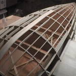
I have decided to strip plank the front end because of the compound curve to the firewall. First two planks glued in place along the bottom center stringer.
GeeBeeR1-2-171
More planking glued in place. I experimented with a few gluing methods and found that using yellow glue on the edges and thick CA on the formers to work the best.
GeeBeeR1-2-172
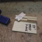
Up to this point I have been making planks like everyone else seems to...I bought the Master Airscrew balsa stripper and glued the 1/4" hardwood stick to the bottom to achieve the angle. Well, what a stupendous plastic piece of crap this thing is...philips screws into plastic to hold the knife blade in place which they don't. Combine that with the fact that you have to drag the thing along your workbench and the blade just moves to wherever it wants to be. So, I made a strip plank cutter similar to the 1/2" stripper I made earlier.
GeeBeeR1-2-173
Bottom strip planking in place and rough sanded. This is as far as I can go until I sort out the aileron torque rods into the fuselage. You can just make out the cut lines for the hatch.
GeeBeeR1-2-174
I popped the hatch out just to make sure it wasn't glued in place. The hatch will be put back in place for final sanding/shaping.
GeeBeeR1-2-175
Starting to add the former tops and stringers.
GeeBeeR1-2-176
More former tops in place back to the start of the cockpit area.
GeeBeeR1-2-177
Former F-6 needs modified to accommodate the new fuselage shape.
GeeBeeR1-2-178
Adding to former F-6.
GeeBeeR1-2-179
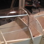
Just getting a feel for where the canopy will sit and marking out some layout lines.
GeeBeeR1-2-180
Making a new F-7A to better match the shape of the canopy which is slightly off from the Haffke plans.
GeeBeeR1-2-181
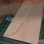
Drawing out the new extended fin leading edge.
GeeBeeR1-2-182
Fin leading edge in place. There is quite a cavernous space here now with the extended tail so I will have to add a little structure in there later.
GeeBeeR1-2-183
Right side stringers in place.
GeeBeeR1-2-184
Left side stringers completed. I added a double stringer where the turtle deck starts for some added gluing area for the sheeting.
GeeBeeR1-2-185
Drawing up additional formers for the fin.
GeeBeeR1-2-186
First former in place.
GeeBeeR1-2-187
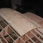
Turtle deck / fin planking in place. Two of the planks didn't want to make the transition from horizontal to vertical so they were pieced in. The gap will be filled with balsa and sanded to shape later.
GeeBeeR1-2-188
Some rear sheeting in place. Larger areas that don't have compound curves get sheeted with 1/8"x6" balsa in lieu of planking.
GeeBeeR1-2-189
Starting the top forward sheeting.
GeeBeeR1-2-190
Sheeting between formers 3 and 4.
GeeBeeR1-2-191
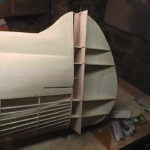
The false former and firewall blocking is completed.
GeeBeeR1-2-192
I used some balsa as filler at the base of the fin on each side.
GeeBeeR1-2-193
Top front planking started. This is as far as I will go until the strut mounts are completed.
GeeBeeR1-2-194
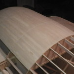
Rear turtledeck / cockpit planking completed and rough sanded.
GeeBeeR1-2-195
Thin coat of filler applied to the rear planking.
GeeBeeR1-2-196
Filler sanded smooth and ready for a final skim coat later.
GeeBeeR1-2-197
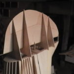
Time to get back on the horizontal stab. Braces added at the stab cutout area.
GeeBeeR1-2-198
Stab cutouts extended through the outer sheeting.
GeeBeeR1-2-199
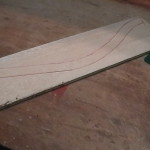
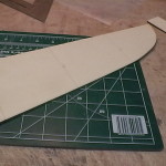
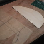
Modifying the stab core to more of a scale outline.
GeeBeeR1-2-200
I've glued the basswood trailing edge in place in order to straighten the horrendous bow in the plywood core.
GeeBeeR1-2-201
Laying out the fuselage cutout on the leading edge.
GeeBeeR1-2-202
The elevator cores have been trimmed square and then a piece added to make up the shape of the R1-2 elevators.
GeeBeeR1-2-203
New elevator shape.
GeeBeeR1-2-204
Hinge components made up and cutouts laid out on the right elevator core.
GeeBeeR1-2-205
Hinges tack glued in place on the elevator half.
GeeBeeR1-2-206
Hinge points installed into the stab trailing edge.
GeeBeeR1-2-207
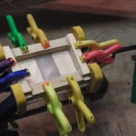
Stab ribs glued in place on the top side of the plywood core.
GeeBeeR1-2-208
Epoxy / milled fiberglass used to secure the hinge points to the plywood core.
GeeBeeR1-2-209
Test fitting the stab with the top ribs in place. It was at this point that I realized the short kit only included enough stab and elevator ribs for one side. I will have to make patterns and cut ribs for the bottom side.
GeeBeeR1-2-210
Another shot of the stab test fit.
GeeBeeR1-2-211
Right side elevator ribs glued in place and sanded to shape. The basswood block will accept the elevator torque rod.
GeeBeeR1-2-212
Epoxy/milled fiberglass used to glue the hinge points in place. I have also put a few bridges over the nyrod hinge sleeve to ensure it doesn't work loose.
GeeBeeR1-2-213
Right side top sheeting in place.
GeeBeeR1-2-214
Laying out the rounded leading edge. The elevators were built tight to the stab so there will be 1/8" of material removed to create a hinge gap.
GeeBeeR1-2-215
Marking center lines to use as a guide while carving/sanding the leading edge to shape.
GeeBeeR1-2-216
Leading edge rough sanded to shape and the hinge pockets enlarged to allow for enough travel.
GeeBeeR1-2-217
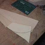
Ready for the gap shroud.
GeeBeeR1-2-218
The original R-2 rudder core laid on top of the tracing for the R1-2 rudder.
GeeBeeR1-2-219
I want to use the original core so I will have to add some 1/8" plywood to make up the difference.
GeeBeeR1-2-220
Additional ply scabbed on and the new rudder core is traced out.
GeeBeeR1-2-221
New rudder core cut to shape.
GeeBeeR1-2-222
Drawing out the rudder hinges.
GeeBeeR1-2-223
Hinges cut out and trial fit to the 1/8" plywood tailpost.
GeeBeeR1-2-224
Back side view of the rudder hinges through the tailpost.
GeeBeeR1-2-225
Tailpost set in place to lay out the lightening / access holes.
GeeBeeR1-2-226
Inner nyrod glued to the leading edge of the rudder core for the hinge pin guide tube.
GeeBeeR1-2-227
Upper tailpost set in place with the rudder core attached.
GeeBeeR1-2-228
Another view of the rudder hinging.
GeeBeeR1-2-229
The back side of the rudder hinges are reinforced with basswood triangle stock epoxied in place.
GeeBeeR1-2-230
Lower plywood tailpost.
GeeBeeR1-2-231
All four rudder hinges in place on the upper and lower tailposts. The split is for the stabilizer trailing edge to pass through.
GeeBeeR1-2-232
Tailposts aligned and epoxied in place.
GeeBeeR1-2-233
Shot of the tailposts with the tape and clamps removed.
GeeBeeR1-2-234
Rudder hinge alignment is complete...time to build this massive rudder.
GeeBeeR1-2-235
Rough shaped rudder ribs glued in place and squared against the tailpost. I am hoping to leave these in place until the bulk of the rudder sheeting is completed. Otherwise, I'm not quite sure how to sheet the rudder without twisting it.
GeeBeeR1-2-236
1/8" balsa sheeting rudder sub-leading edge glued in place.
GeeBeeR1-2-237
Transferring the tailpost shape to the rudder sub-leading edge is proving to be a little tricky.
GeeBeeR1-2-238
Left side of the rudder ribs and leading edge shaped.
GeeBeeR1-2-239
Bottom left side of the rudder.
GeeBeeR1-2-240
All ribs and leading edge shaped.
GeeBeeR1-2-241
The rudder was shaped while it was in place on the fuselage. Here I have marked a cut line 1/8" in to allow for the sheeting.
GeeBeeR1-2-242
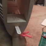
Time to lay out the position of the rudder control horn and get the servos in place.
GeeBeeR1-2-243.
Drawing out the rudder servo tray.
GeeBeeR1-2-244
Servo tray trial fit in place.
GeeBeeR1-2-245
A servo rail box is epoxied up in place over the servo tray to ensure a good fit in the fuselage.
GeeBeeR1-2-246
Servo rails are pinned with toothpicks and filleted with epoxy / milled fiberglass.
GeeBeeR1-2-247
Trial fit of everything in place inside the fuselage.
GeeBeeR1-2-248
Shot from under the fuselage. The servo rail box has been epoxied in place with 2 screws on each side to hold it in place until the epoxy cures.
GeeBeeR1-2-249
Drawing out the shape of the rudder control horn.
GeeBeeR1-2-250
Control horn cut out of 1/8" plywood. I am setting this up with a solid pushrod pull/pull at this time but may change it to pull/pull cables later.
GeeBeeR1-2-251
Slot cut into rudder core to accept the control horn.
GeeBeeR1-2-252
Control horn trial fit in place.
GeeBeeR1-2-253
Control horn tacked in place and the sub leading edge trimmed out to make room for the clevises.
GeeBeeR1-2-254
1/4" basswood triangle stock epoxied on all four sides of the control horn will make sure it stays in place.
GeeBeeR1-2-255
Because the rudder has been enlarged considerably, I am adding another rib mid way out to stiffen up the sheeting a bit.
GeeBeeR1-2-256
Beginning of the rudder sheeting.
geebeer1-2-257
Rudder ready to work out the leading edge.
geebeer1-2-258
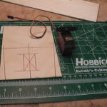
Laying out servo locations in the horizontal stabilizer core.
geebeer1-2-259
Basswood epoxied to the top of the stab core for servo screws.
geebeer1-2-260
Bottom view of stab with servos mounted. The servos will be accessible through the tail end with the rudder removed.
geebeer1-2-261
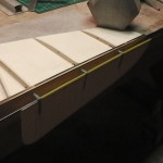
Elevator hinge gap shrouds made similar to the ailerons.
geebeer1-2-262
Right side shrouds in place.
geebeer1-2-263
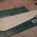
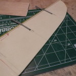
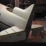
With the shrouds completed and leading edge rough shaped, the stabilizer is ready to be permanently mounted to the fuselage.


Leave a Reply
Please note: Comment moderation is currently enabled so there will be a delay between when you post your comment and when it shows up. Patience is a virtue; there is no need to re-submit your comment.