Great Planes Yak 54 ARF
The Great Planes Yak 54 3D ARF is the project that I settled on for myself in order to get some flying time in this year. Its been about 3 years since Ive done much actual flying so I wanted a “throw it in the trunk and go” electric since it will be a year or two until any of my larger scale projects are ready to take off. This is definitely a departure from the norm for me as I’m not used to working with these micro parts. Having large hands is surely a handicap here.
yak54001
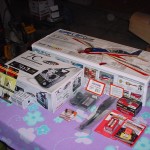
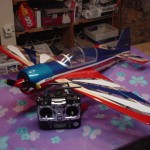
The Tower Hobbies Yak 54 Ultimate Combo comes with everything you need to get in the air. Ive made a few substitutions to the standard combo...I upgraded the radio system to the Futaba 7C so it is a little more future friendly and also substituted an AC/DC charger for the DC one that was included.
yak54002
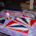
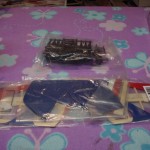
As it is out of the box...typical of most ARFs, the covering needed shrunk down a bit but other than that all looks good.
yak54003
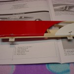
Starting off with hinging the ailerons. The included hinges were a little small and thin for my tastes so I ended up cutting new hinges from some stock material.
yak54004
Right aileron hinged and ready for servo setup.
yak54005
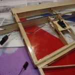
Left aileron servo installed.
yak54006
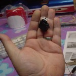
As stated before...big hands are a definite handicap working with these micro servos.
yak54007
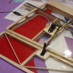
Left aileron linkage setup. The kit comes with all the necessary linkages and carbon fiber pushrods. Not sure yet if I completely trust the screw clamp on the clevises so I'm thinking some thin CA on those might be in order.
yak54008
The wings are permanently glued to the fuse on this model. I had considered making them removable but after seeing the size of it I decided against that.
yak54009
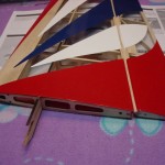
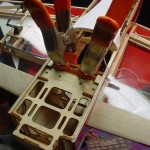
The bottom side of the wing joiner. Plywood braces dont get glued at this step but are just there to hold the spars together.
yak54010
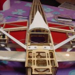
Plywood wing joiners epoxied in place and the landing gear mounted. The blind nuts for the gear are factory installed. Be sure to put a drop of thread lock on each of the bolts to prevent them from breaking loose.
yak54011
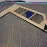
Test fitting the elevator joiner wire. The joiner wire does not get glued at this point.
yak54012
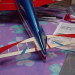
Horizontal stabilizer installed. After checking measurements to square it up to the fuse, a healthy dose of thin CA is all that is needed to glue it in place.
yak54013
The left elevator half with the control horn installed.
yak54014
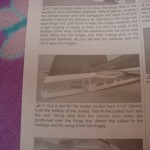
Although Great Planes tech support disagrees that there is any problem, I ran into a situation with the rudder control horn. You can see here that the instructions say to mount it 1 1/2" up from the bottom of the rudder.
yak54015
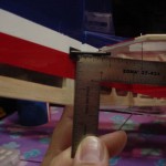
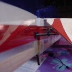
The picture is a little dark but you can see that the rudder horn is mounted 1 1/2" up from the bottom of the rudder.
yak54016
At this location, the rudder horn clearly interferes with down elevator with even a slight deflection.
yak54017
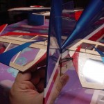
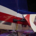
Even before using 3D rates you can clearly see that the elevator can become trapped by the rudder horn. This is without the rudder pushrod even hooked up which makes the situation worse.
yak54018
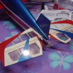
Elevator halves joined and hinged.
yak54019
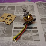
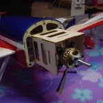
The Rimfire .10 electric motor. Be sure to use thread lock when installing the motor mount and also the prop hub.
yak54020
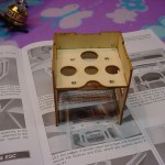
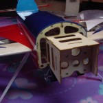
The motor box goes together quickly with tab and slot pieces. Be careful here that you end up with right thrust after gluing everything together....the motor mounting holes are NOT centered on the firewall. This is just glued with medium CA for now but I will fillet glue it later with an epoxy/microballoon mixture.
yak54021
Motor box epoxied in place.
yak54022
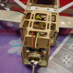
Motor mounted. Once again, threadlock is important here.
yak54023
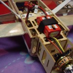
The speed control is mounted to a fuse former with a zip tie. You could also use a small piece of velcro here.
yak54024
I also used a zip tie to mount the receiver to the face of the wing joiner.
yak54025
Hard to see but this pic is showing the 90 degree mounting of the two antenna on the Futaba FAAST receiver. I glued a short piece of balsa to the former and to the fuse side and simply taped the antenna in place.
yak54026
Velcro strap for the LiPo battery held in place with a little medium CA.
yak54027
Test fitting the cowling and getting the prop clearance set.
yak54028
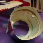
A nice fillet of medium CA to hold the cowl ring in place. The magnets are also held in place with CA.
yak54029
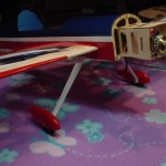
Wheels and wheel pants all assemble onto the landing gear with a bolt and two nuts. Use threadlock on the outer nut to prevent it from tightening on the wheel.
yak54030
Both wheel pants installed. I dont think these will hold up very well in the grass but should do fine on a hard surface.
yak54031
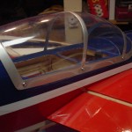
The instructions call for the canopy to be taped on with clear tape but I wasnt crazy about that idea. I decided to mount the canopy with 6 small buttonhead screws so that I can remove it at anytime to fiddle with the servos if necessary.
yak54032
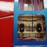
Rudder and elevator servos mounted. Ive also put a drop of thin CA under each tab just in case the screws decide to break through the edge of the thin ply mounting plate.
yak54033
Ask and ye shall receive....Great Planes support sent out a whole new tail set.
yak54034
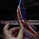
The new rudder horn is mounted 1" above the bottom of the rudder instead of the 1 1/2" that the instructions call for. You can see from this pic that it just clears the elevator with 3D throws set.
yak54035
Another view of the new rudder/horn location.
yak54036
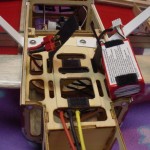
2 little velcro tabs so the batt stays put. Ive also added a ply plate because the front of the batt fell right in the lightening hole and wanted to teeter when strapped down. I also needed a little nose weight so the ply didnt hurt.
yak54037
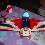
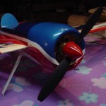
Ready for her maiden.

Leave a Reply
Please note: Comment moderation is currently enabled so there will be a delay between when you post your comment and when it shows up. Patience is a virtue; there is no need to re-submit your comment.